How it Works
The Cool Tube® MKII works based on a drop of the temperature of the compressed air delivered to the unit. Typically, underground mines compressed air temperatures in the warmer months range from 24 – 28°C, due to no exposure to direct sunlight on delivery lines.
As standard, The Cool Tube® MKII is designed to give a temperature drop of 24 – 30°C (pending model), of the compressed air inlet temperature. For this reason, it is of great benefit to know what the inlet temperature that you will be working with is, to better understand the resulting temperature of the cold air from The Cool Tube® MKII.
If using a 180 CFM unit and the compressed air inlet temperature is 26°C, then the expected cold air outlet temperature blowing from unit should be 0 – 2°C on average.
Additionally, for the best performance, an inlet compressed air pressure should be between 6 – 8 Bar / 85 – 115 PSI. The option to install a water trap or filtration in the compressed air circuit is based on the sites understanding of their compressed air quality. Compressed air laden with moisture will reduce the overall efficiency and performance or the units. Moisture and general oil mist particles in the compressed air, will tend to be exhausted from the warm end as priority but some will still be released through the cold end discharge.
* The Cool Tube® MKII cold end outlet air temperature is a linear temperature drop from the compressed air inlet temperature.
NOTE: The Cool tube® MKII will continue to function as intended if not tampered with, installed and used as directed.
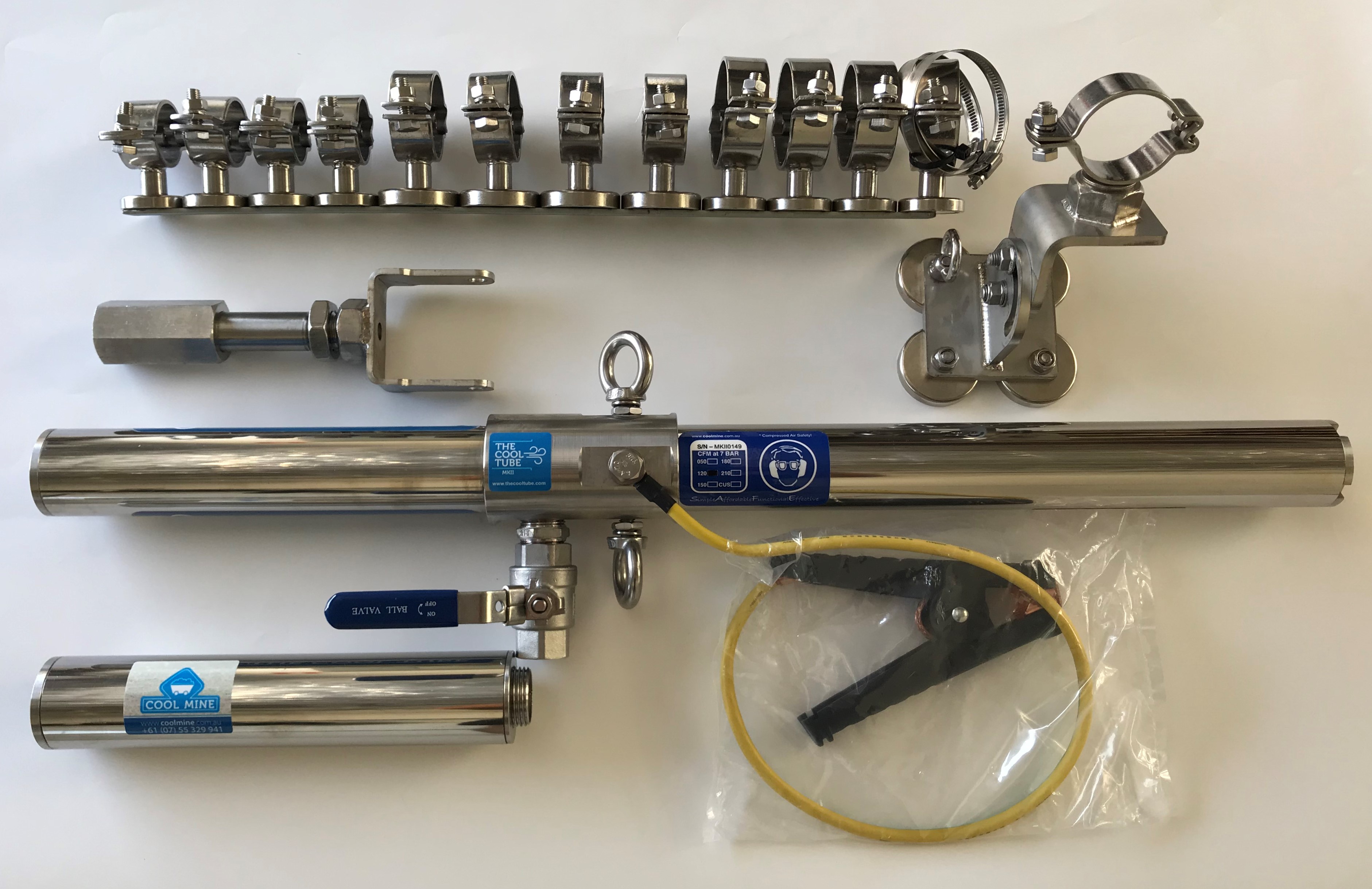
The Cool Tube® MKII User Instructions
- Install the supplied mounting post and bracket assembly to the desired location. Attach THE COOL TUBE® MKII using the supplied 2 x M10 bolt fasteners, to two of the M10 female holes located around the axis of the main distributor body. Set the desired angle and tighten the 2 x M10 bolt fasteners.
- Connect the site standard minimum1″compressed air supply and secure as per site standard. Ensure the compressed air line supply has no restrictions or reductions to the THE COOL TUBE® MKII. Keep the hose length to the minimum required. Do not ‘tee’ additional compressed air driven devices off the line.
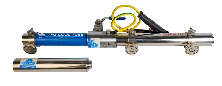
- Screw on the 1″ Male BSP thread of the 250mm extension silencer, to the cold end discharge of THE COOL TUBE® MKII.
- When installing the 51mm / 2 inch diameter warm exhaust extension (Recommended for maximum dBA reduction) hosing on the warm air discharge ventilated heat shield, ensure that the hose length has minimal “dips” that could reduce the efficiency of THE COOL TUBE® MKII, by allowing any water in the line to collect. A Cool Mine exhaust baffle, 250mm extension silencer, or a restriction, such as course stainless steel wool in
the end of the bull hose to reduce any residual noise is an effective addition to the final installation. - Connect the earthing cable clamp to a grounded location if required by site risk assessment. THE COOL TUBE® MKII is fully electrically bonded with no non-conductive components used. An earth clamp has been added as a control when used in hazardous environments.
- Ensure that the appropriate PPE and precautions are taken as per the “Page 1 Safety Notes” prior to energising the
compressed air supply to THE COOL TUBE® MKII. - Slowly turn on the compressed air supply. The cold end discharge air supply should be immediate; however steady state temperatures may take up to 2 minutes to settle. If installing a cold end extension hose or duct, ensure that the cross sectional area of the hose or ducting is greater than the cold outlet of THE COOL TUBE® MKII. A minimum 2″ or 51mm ID bull hose as used on the warm end exhaust is the minimum recommended. A back pressure of greater than 4 PSI on the cold end will reduce the performance of THE COOL TUBE® MKII.
- THE COOL TUBE® MKII can be flushed with water for internal cleaning if required.
- Always ensure that THE COOL TUBE® MKII has been secured and or mounted correctly and that the immediate area has been demarcated or highlighted if the units have been mounted in a location that can interact with people and or equipment.
Base Mount Magnet User Instructions
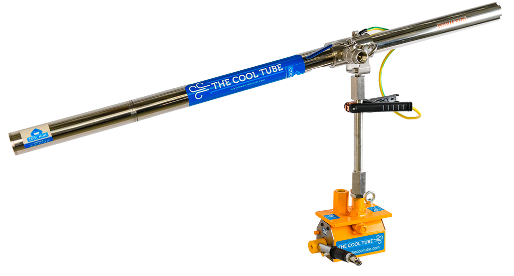
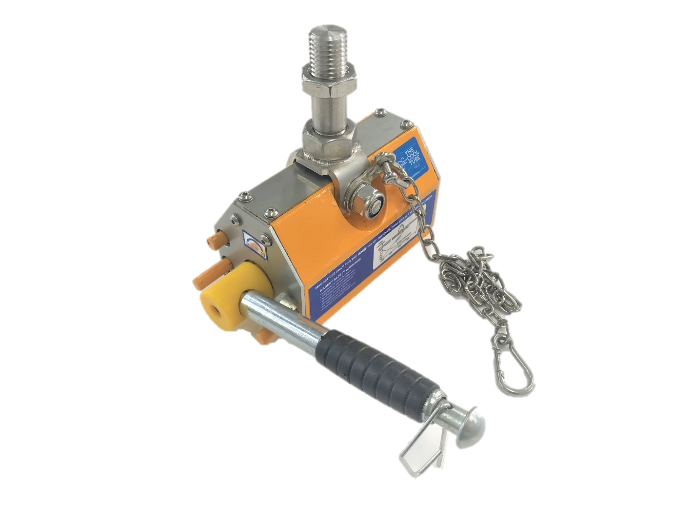
Note – The holding strength of the Base Mount Magnet is dependent on good and full surface contact and the thickness of the parent metal being adhered to. Mounting plate thickness >5mm for bench top applications and >10mm for maximum holding strength in high impact, vertical or overhead applications. The Base Mount Magnet is not a lifting device and no other items are to be supported by it.
- Place the base mount magnet on a clean flat suitable ferrous surface, turn and engage the magnet lever into the “ON” position. test effectiveness of the magnetic hold. Insert the supplied minsup clip into the hole on the lever handle to prevent unintended operation of the lever.
- Screw THE COOL TUBE® MKII onto one of the threaded mounting options on the base mount magnet.
- Ensure to connect the safety tether from the base mount magnet, to a fixed suitable and effective mounting point, that will contain the unit if the magnetic connection or other is compromised. The tether is intended only to support the fall of THE COOL TUBE® MKII, due to poor magnet mounting technique or external interference and should not be used for any other manner.
- Test connection strength while tethered before leaving fully unattended.
- Demarcate or barricade the area as required if vertically or overhead mounted and poses a risk to persons or interaction with mobile equipment.
Flush Magnetic Mount
Let your imagination be the guide for the endless applications of this installation method in your workplace!
- Secure 3-4 stainless steel 51mm ID tube clamps with potted magnets to THE COOL TUBE® MKII. Do not fully tighten to allow to slide around THE COOL TUBE® MKII, so as all potted magnets self align to the ferrous surface being attached to.
- Ensure the ferrous >5mm thick steel material being used as the support base is clean and flat for the potted magnets to magnetise to.
- Place THE COOL TUBE® MKII on the ferrous surface that is no less than >5mm thick material to ensure good magnetic adhesion.
- Tighten the tube clamps with the potted magnets to secure THE COOL TUBE® MKII.
NOTE – this installation method is a useful application for mounting on equipment such as
- Longwall chocks / shields
- Continuous Miners
- Jumbo’s
- COB’s – Fixed and Mobile Underground Coal Mining Self Rescuer Change Over Bases.
- Refuge Chambers
- Containers
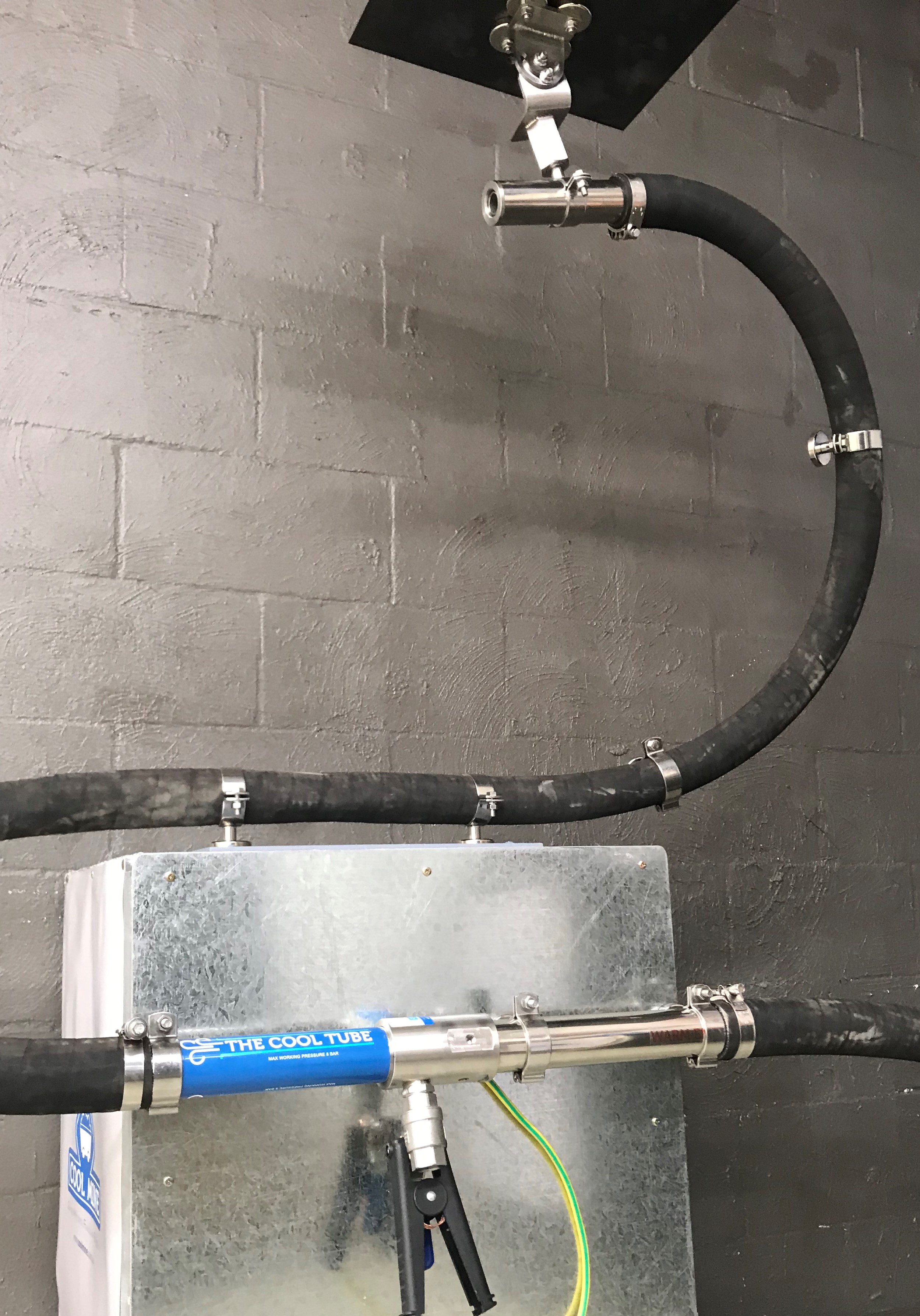
Application in this method allows for the units to be permanently mounted in a safe secure location, with the cold and warm air being delivered to their respective areas via separate 2-inch hoses attached either end as per below.
Extension Adaptors User Instructions
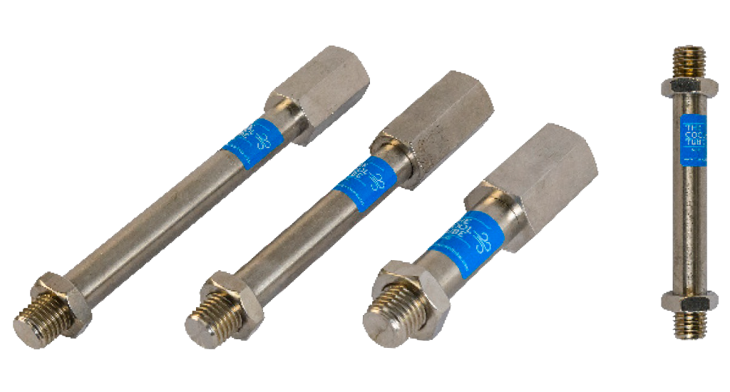
- Screw male / female end of adaptor onto strata bolt, base mount magnet, hand rail mount assembly or other mounting point.
- Screw male / female end of adaptor onto The Cool Tube® MKII adjustable arm.
- Tighten firmly
Additional Accessories
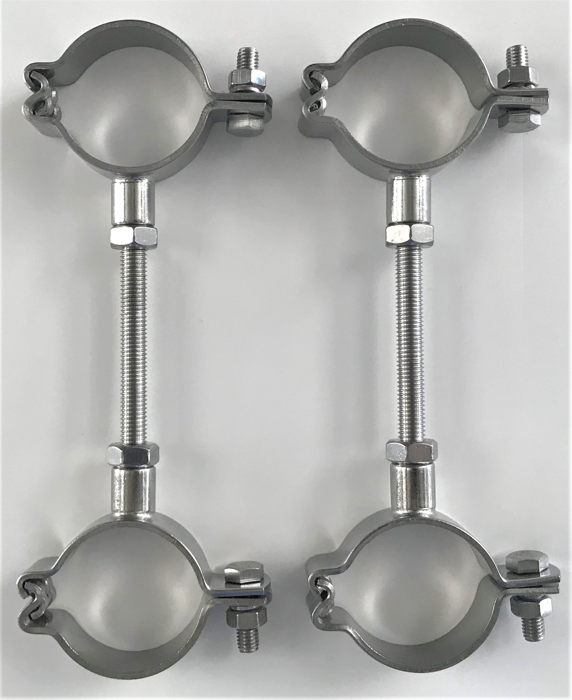
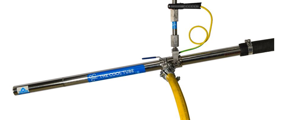
Coupling Clamp Kit for Twin Shooters
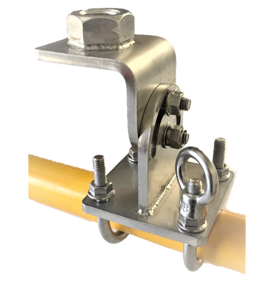
Adjustable Handrail Mount
Extension Silencer User Instructions
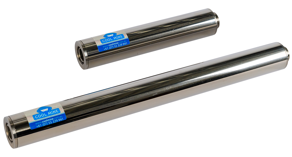
- Screw male end of extension silencer into female 1” BSP cold discharge of The Cool Tube® MKII.
- Hand tighten firmly.
Using Twin Shooters?
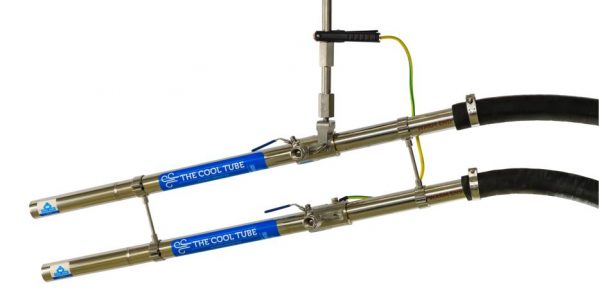
If two or more units of THE COOL TUBE® MKII, are installed in parallel using the stainless steel coupling assemblies, ensure a separate compressed air supply hose is run to each unit. If using a larger compressed air supply such as 2″ hose, to run the main supply line to the units, then a “tee” may be used to reduce back to 1″ line for the dual supply into each unit. Various configurations of this set up should be trialed to best suit your application and compressed air volume availability at the location.